Flying Car Chassis | FEA Analysis
- Mar 8, 2018
- 2 min read
Updated: Dec 14, 2018

One of my favourite modules in my university course has been FEA or Finite Element Analysis. It has given me a tool-set that opens up many opportunities in providing validation for my CAD work. This module also present a project that seem impossible at first glance but became achievable once we have learnt about it. This visible progression is very empowering!
This project began with a specific brief. Design the chassis for the Pal-V liberty flying car.

This amazing flying car requires some amazing engineering to fly effectively. The brief required that the chassis should be able to survive a worst-case scenario landing. We should also be able to support the forces of the rotor and we needed to have a natural frequency outside of a specific range.
I worked with a small team and we set out to design a range of different designs. We first ha to fully understand the parameters of the problem. We created free body diagrams of each of the areas of interest.

We then used created frames that surrounded a no-go area. These frames ranged from minimalist to extreme complexity.


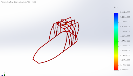
We iterated many times and tested the different situations. These are some example of the results of our FEA analysis.

Here we can see the force propagate through the chassis to create stress on the other wheel. This is quite strange if considered in context, however, this was part of the parameters for the problem. The forces are applied to the right wheel and we consider that the left wheel is fixed in place. This makes the system easier to asses.

Here is another test. The natural frequency of the chassis needed to be above or below a range of frequencies that the oscillation of the rotor will produce.
Finally this test is to find out whether the structure could withstand the forces of the rotor. This image shows an exaggerated displacement of the rotor during the rotation of the rotor.
Solution
This project was fun but exhausting. We found after many hours of iterating the design that there was no way of actually completing the problem with the materials and pipe profiles from the brief.
We found that a solution could be found, however if the profile of the pipes was made thicker. We suggested that the increase in weight that the additional material would introduce would be counterbalanced by the strength of the system.
We presented out solution of the university cohort and the assessors. The project was interesting because the solution was impossible. This required some additional soft skill development as the best solution was to simply come back and explain why it couldn't be done in as set out in the brief but could be done if a small change was made.
Thank you for reading!


Comments